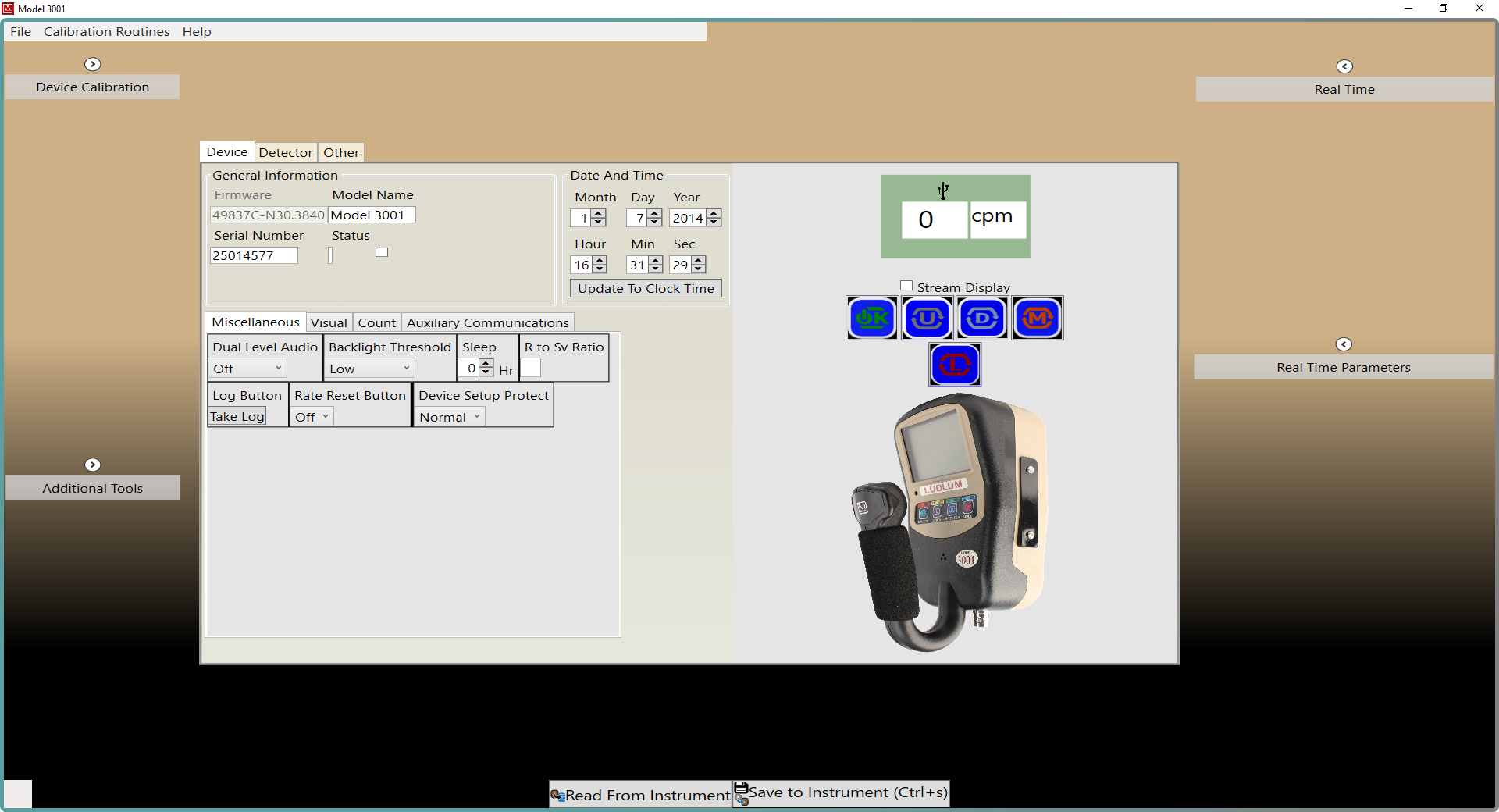
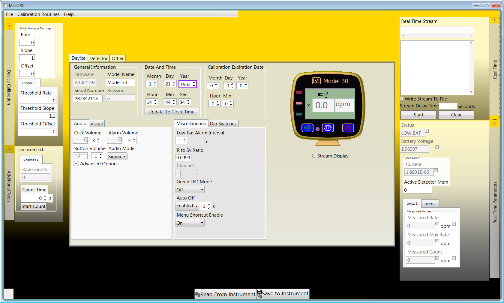
Lumic 1 Calibration Software
This article is about the Lumic 1 Calibration Software. A future article will cover the new Lumic 2 Calibration Software.
Lumic 1 is a useful tool that provides the ability to read and write important parameters via a USB port in the Model 3000 Series and Model 30 family of instruments. Instrument parameters may be loaded or saved to files, and an instrument parameter report may be printed. The software also allows streaming and viewing of current readings and measurements of the instrument. Two "wizard" features include a gamma exposure/dose calibration routine and an automatic plateau. The calibration routine wizard leads the user through the calibration steps for a gamma radiation source. The plateau wizard automatically records data at different detector voltages to determine the correct voltage for operation. Using this software makes instrument calibration very quick and easy, requiring less work than calibrating most analog instruments.
Minimum Requirements
- Supported Operating Systems: Windows 7 and higher (32-bit and 64-bit versions)
- Microsoft .NET Framework 4.5 (installed on most machines by default)
- Computer with Intel or compatible 1 GHz or faster processor (2 GHz or faster is recommended)
- Minimum of 256 MB of RAM (1 GB or more is recommended)
- 1 GB of free hard disk space
Installation
Lumic 1 is included as part of the Lumic Calibration Kit (PN 4519-865). This kit includes both versions 1 and 2 of the Lumic Calibration Software, as well as two USB cables, one for Model 3000 Series instruments and one for the Model 30 family of instruments. See the table below for the firmware requirements and the software version that can be used with each instrument.
| Lumic Calibration Software | Compatible Models | Required Firmware |
|---|---|---|
| Version 1.0 | 30, 30-4, 30-6, 30-7, 35, 79 | N/A |
| 3000, 3001, 3005, 3006, 3019, 3276 | N34 or lower | |
| 3002, 3277 | N12 or lower | |
| Version 2.0 | 3000, 3001, 3005, 3006, 3019, 3276 | N40 or higher |
| 3002 | N20 or higher | |
| 3003, 3014, 3078 | N/A |
To install Lumic 1, run the installer MSI from the installation CD and follow the on-screen prompts.
On 64-bit machines, the default installation location is: C:\Program Files (x86)\Ludlum Measurements, Inc\Ludlum Lumic Calibration.
On 32-bit machines, the default installation location is: C:\Program Files\Ludlum Measurements, Inc\Ludlum Lumic Calibration.
Firmware Updates
If your Model 3000 Series or Model 30 family instrument does not meet the firmware requirements listed in the table above, you can update the firmware on your instrument using our free Lumic Firmware Updater. Instructions and firmware downloads are available on the Software & Firmware Downloads page.
Please note that for Model 3000 Series instruments, you must determine the version of the instrument's main circuit board. To do this, you must open the instrument housing and find the number on the circuit board. Contact us if you have questions about how to access and locate the board number for your instrument.
Instrument Connection Window
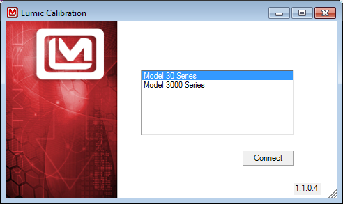
After launching the Lumic 1 software, a window will appear that shows a list of compatible instruments currently connected to your computer. Select the instrument name in the list and click the "Connect" button to enable communication between the software and the instrument.
Main Window
Once the communication link between the software and the instrument has been established, the instrument main window will appear.


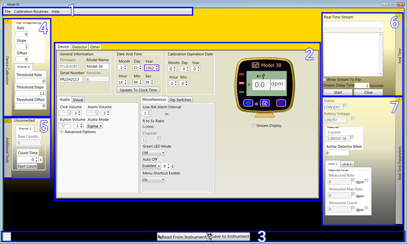
The default screen has seven main sections, highlighted in the screenshot below:
Sections
- Main Toolbar
- Instrument Parameter Tabs Control
- Status Bar
- Device Calibration
- Additional Tools
- Real Time Readings
- Real Time Parameters
Calibration Routines
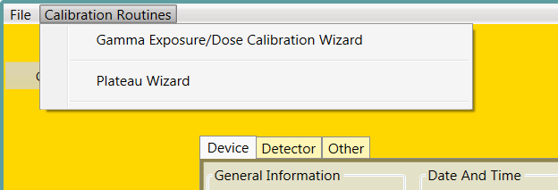
The remainder of this article will only focus on the calibration wizards, which are found in the main toolbar under "Calibration Routines". For more information about the other features available in this software, download the Lumic 1 Calibration Software Manual.
Gamma Exposure/Dose Calibration Wizard
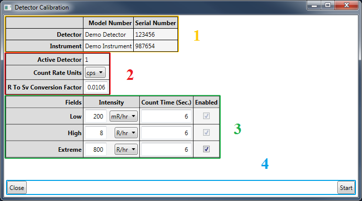
In the main toolbar, select "Calibration Routines" and then "Gamma Exposure/Dose Calibration Wizard". This will open the following screen:
Sections
- Instrument and Detector Information
- Units Settings
- Radiation Field Settings
- Control Buttons
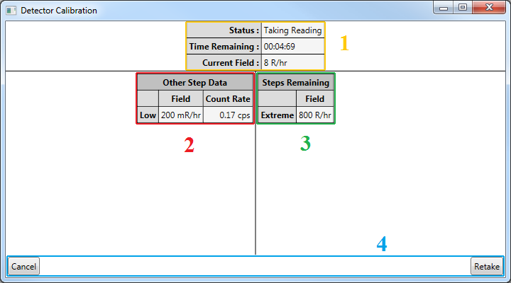
This screen lists the actual calibration points, among other information. To begin the calibration process, click the "Start" button. You will then be prompted to place your instrument or detector in the corresponding radiation field.
Sections
- Procedure Status
- Readings from Previous Steps (not shown if no previous readings)
- Remaining Steps (not shown if no steps remain)
- Control Buttons
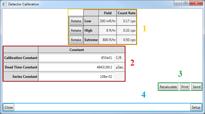
After you have taken readings at each calibration point, the next screen will display the calculated calibration constant, the dead time constant, and the series constant. If desired, you have the option to retake readings at any calibration point. If you are satisfied with the results, click the "Send" button, and the parameters will be saved in your instrument.
Sections
- Summary of Readings
- Calculated Constants
- Recalculate, Print & Send Buttons (for constants)
- Control Buttons
Plateau Wizard
Selecting this option will open a window that will lead you through a plateau procedure, which is commonly done to find the desired operating voltage for a particular detector. This procedure involves taking measurements with the detector at different voltages. The measurements at each voltage may include no radiation source (just background radiation), and/or one or more radiation sources. For example, a typical plateau for a scintillation detector might involve taking data from 600 to 1000 Vdc, measuring background radiation and a 241Am radiation source. Refer to the calibration procedure for your individual detector(s) to determine the appropriate voltage range and radiation source(s) to use.
The criteria for determining the desired operating voltage is up to the user; this Plateau Wizard merely automates the measurement process.
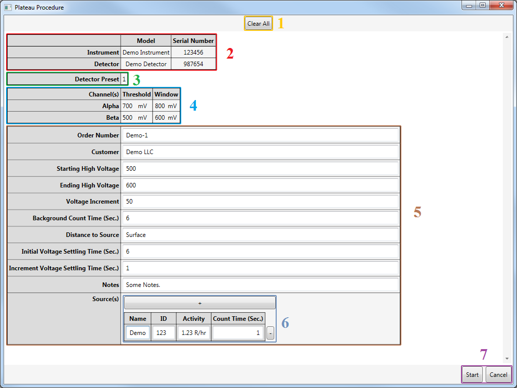
Sections
- Clear All Button
- Instrument and Detector Information
- Detector Preset
- Channel Settings
- Plateau Procedure Settings
- Source List
- Control Buttons
Several parameters can be set, including:
- Starting High Voltage: The lowest (and initial) high voltage to test.
- Ending High Voltage: The highest (and final) high voltage to test. Must be greater than the starting high voltage.
- Voltage Increment: The amount the high voltage will change per step. The difference between the starting and ending high voltage must be divisible by this value.
- Background Count Time: The amount of time to take the background reading for each step.
- Source(s): The list of sources the procedure will use to display the plateau.
After the counts have been taken, a screen will show the results:
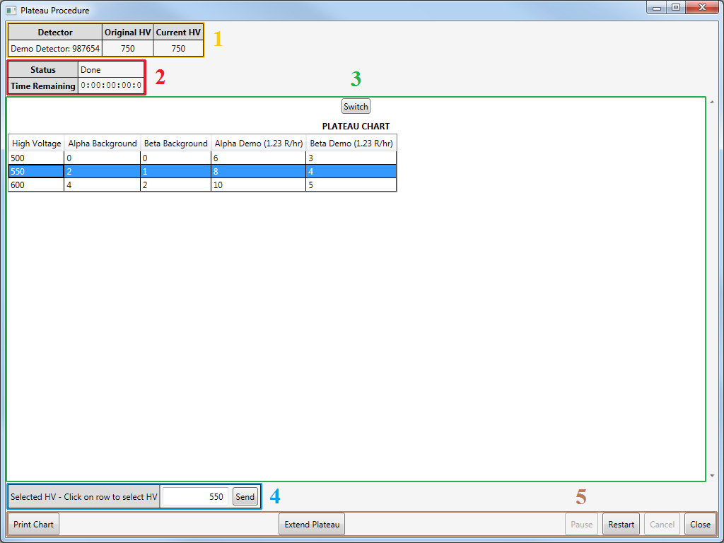
Sections
- Detector HV Settings
- Procedure Status
- Plateau Data
- Selected HV Setting
- Control Buttons
To view the readings in a graph rather than a table, click the "Switch" button.
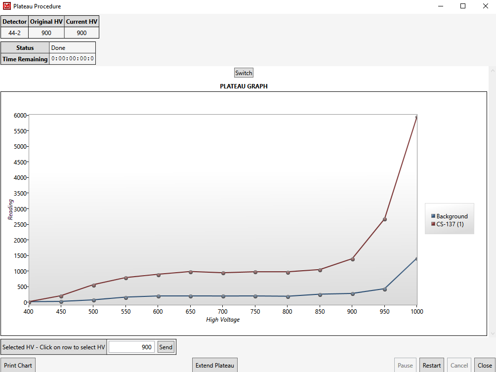
At the bottom of the screen, the suggested operating voltage determined by the software will be displayed. You can use this value, or you can input the operating voltage you prefer. Clicking the "Send" button will then set the operating voltage of your instrument.
If you have any questions or inquiries about the Lumic 1 Calibration Software, please contact us.
